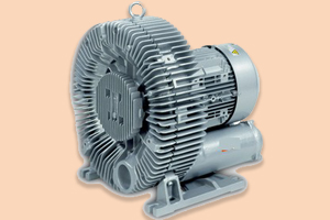
Pneumatic Conveying Blowers
Pneumatic Conveying Blowers, Hot Air Blowers, High Pressure Blowers,Medium Pressure Blowers, Pressure Blowers, High Vacuum Blowers.
Pneumatic Conveying typically refers to the movement of dry powders or pellets from point A to point B in a pipe or tube by means of a difference in pressure.
The method has been practiced by industrial manufacturing and utilities for many decades.
Since the invention of PD (positive displacement) blowers the utilization of air to transport materials throughout the globe has been popular.
Blower assisted pneumatic conveying systems are simple and eminently suitable for transport of powdered and granular materials in factories and chemical plants.
Normally Pneumatic Conveying Blowers/ Medium Pressure/High Pressure/Vacuum Blowers(Also known as Regenerative / Side Channel / Turbine / Vortex Blowers) are associated with medium pressure and vacuum applications. However now specially built Higher Pressure / Vacuum Blowers are available for such applications.
| Power Rating : | - |
| Maximum Flow : | - |
| Maximum Pressure : | - |
| Maximum Vacuum : | - |
USEFUL CONVERSIONS DATA:
- 1 Mbar= 0.402 in H2O = 10.2mm H2O=0.0295 in.Hg=0.75 mm Hg = 0.0145 psi =100 Pa=10 daPa = 100 N/m2 = 0.750 Torr
- 1 M3/Hr.= 0.588 CFM.= 35.31 Ft3/Hr = 16.67 L/Min
- 1 KW = 1.34 HP = 1000 W
USEFUL CONVERSIONS LINK:
Features Of Blowers
Pneumatic Conveying Blowers / Hot Air Blowers / Ring Blowers / Side Channel Blowers / Regenerative Blowers / Turbine Blowers / Vortex Blowers / Vacuum Blowers / Medium Pressure Blowers /High Pressure Blowers / High Vacuum Blower / Ring Compressor / Lateral Channel Blowers Data Summary
The Hot Air Blowers / Ring Blowers / Side Channel Blowers / Regenerative Blowers / Turbine Blowers / Vortex Blowers / Vacuum Blowers / High Pressure Blowers / High Vacuum Blower / Ring Compressor / Lateral Channel Blowers are suitable for all those applications requiring considerably higher pressure, than those which can be achieved using centrifugal fans. Side Channel exhausters are used in all those applications requiring an operating vacuum higher than the one achievable by a fan, but not as to require the use of a vacuum pump. The rotating parts are not in contact with the casing. There is, therefore, no friction during operation and thus no internal lubrication is necessary.
Pneumatic Conveying Blowers with inlet air temperature below 70deg. C. and direct mounting are compact in construction, and run with high-speed motors.? Such blowers are mostly used for better mixing of fresh air to the furnace for a better combustion.
The other main features are:
- Higher Pressure Ratio
- 100% Oil-Free Continuous High Pressure Air Flow
- Blower Can Be Used For Pressure Or Vacuum Applications
- Low Noise Level (65dba Normal, 85 dba Max.)
- 110% Overload Protection
- ±10% Voltage Fluctuation Tolerance
- Rated For Continuous 24 X 7 Duty
- IP 55 Protection
- Class F Insulation
- Motor Design compatible with VFD Drive For Easily Accommodating Operating Condition Changes
- Impeller Directly Mounted on Motor Shaft Eliminates Maintenance Issues Like Change Of Gears, Pulleys, Belts
- Pressure Die Casted Aluminum Alloy Body, Impeller & Rotor
- Dust Proof Polymer Shaft Seal
- Low Temperature Rise
- Pulsation- Free Discharge
- Light And Compact But Sturdy Aesthetically Appealing Design
- CNC Machined For Close Tolerances And Better Performance
- Dynamically Balanced Impeller Assembly For Longer Vibrations Free Life
- High Temperature Grease Filled And Double Sealed NSK/SKF Bearings
- For Trouble Free Operation For Long Periods
- Space Efficient Easy Installation In Vertical Or Horizontal Position
- With Built In Inlet And Outlet Silencers
- Minimal And Simple Maintenance
- Suitable For Environmental Protection
Application Of Blowers
The Pneumatic Conveying Blowers / Hot Air Blowers / Ring Blowers / Side Channel Blowers / Regenerative Blowers / Turbine Blowers / Vortex Blowers / Vacuum Blowers / High Pressure Blowers / Medium Pressure Blowers /High Vacuum Blower / Ring Compressor / Lateral Channel Blowers are suitable for very wide field of application some of them are
-
Waste Disposal / Slurry Declogging In Waste
-
Pneumatic Conveying of Solids / Liquids
-
Vacuum Transfer of Components / Sheets / Liquids
-
Blowing Away Debris / Sucking Away Debris
-
Industrial Vacuum Cleaning
-
Furnace Fuel Burning / Oil Atomization
-
Air Bearing / Air Mattress
-
Medical / Dental Suction Units
-
Air Sampling / Monitoring Equipments
-
Cable Pressurization
-
Liquid / Semisolid dispenser
-
Food Processing and Packaging Applications
-
Sorting / Counting of Cards / Envelopes / Papers
-
Beverage Bottling / Labeling / Drying/Ink Jet Coding
-
Safe and Economical Personal Cleaning Solutions
-
Environmental / Pollution Control and safety equipments
-
During Printing Feed / Transfer of Paper Sheets / Ink Drying
-
Agitation of Liquid Bath for Vegetables and Fruits Washing
-
Provide Air Cushion to Handle Delicate Material like Eggs / Glass
-
Air Curtain, Protection from Dust Ingress and Isolation applications
-
Agricultural Pesticides and Fertilizer Mixing and Spraying Applications
-
Keeping Yarn / Threads / Product in place during processing / sewing / knitting
-
To Suck Debris / Gases from Clean Rooms / Enclosed Spaces /
Tunnels / Laboratories -
To Agitate and Aerate Water in Spa / Whirlpool/ Swimming Pool / Fishing Tanks / Aqua Culture Tanks / Plating Tanks / Concrete / Laundry


